Why use an ADMET Test System in your test lab? To answer that, you must first ask yourself, "What do my customers want?"
Customers want to verify their material composition and properties before use in manufacturing
Customers want to certify materials compared to competitor's materials
Customers want to gain valuable insight that could directly effect production process
Customers want to determine cause of product failure
In order to deliver these services to your customers, you need the following:
Testing Systems that are easy to use
Testing Systems that are low maintenance
Testing Systems that produce accurate, repeatable results
Testing Systems that come from manufacturer's who are supportive and who understand materials testing
Access to manufacturers that have a range of grips, fixtures, and accessories to meet the needs of a wide variety of testing applications
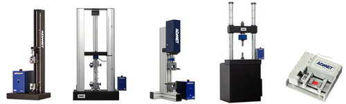
ADMET is a global manufacturer of Universal, Fatigue, Torsion, and Biaxial Testing Machines. The greatest advantage for test labs to use the ADMET equipment is the RANGE of our test frames and the POWER of our MTESTQuattro PC-based servo-controller.
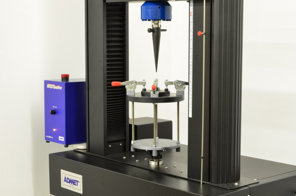
A puncture strength test is performed simply to determine resistance something is to being punctured. Performing a puncture test on a universal testing machine (tensile / compression tester) is a highly accurate and repeatable method.
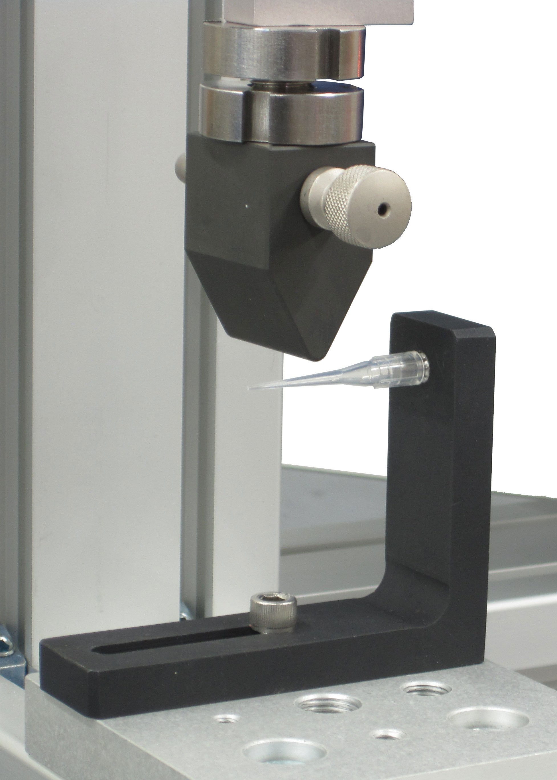
A pipette (also spelled pipet or pipettor) is used to aspirate and dispense fluids in wells for analysis and further testing. There are many types of piston pipettes, but all work on essentially the same principle; hand or mechanical pressure on a piston or plunger working over a fixed length in a cylinder forces a pre-determined volume of liquid out of the orifice of the pipette. Pipettes are used to hold body fluids, oily fluids, concentrated acids, nucleic acids, and volatile compounds.
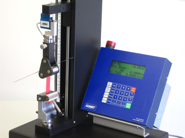
The floating roller peel test is one of many types of tests designed to measure the average peel force of an adhesive or other bonding agent. The other common peel tests are the 90 degree, 180 degree, and T-Peel. Although not suitable for every application, the floating roller is a very accurate and easy method to obtain average peel force values.
For over twenty years, ADMET has been designing state of the art testing systems for a range of industries. From plastics and adhesives to ceramic and metals, ADMET has established itself as a standard bearer in the world of material and device testing.
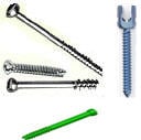
Bone screws are designed to be inserted into bone or bone-like material to stabilize the area. The screws are subjected to different loads as the body moves and as the bones heal. This standard specification is used to determine how much force is required to cause a failure, either a break or removal, from the bone material. This method is used to compare uniformity of different screws.
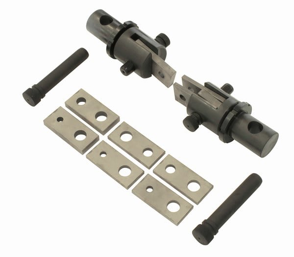
Small titanium, plastic, ceramic, and composite parts are crucial to the assembly of medical devices, medical parts for orthopedics, and dental devices. Many ASTM and ISO standards outline the test procedures and sample preparation. There are many references on the ADMET blog site.
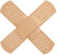
Why is this important? Companies and Universities spend R & D dollars testing various adhesives to determine which one will adhere to skin, but not be painful to remove.
Dental composite resins are types of synthetic resins which are used in dentistry as restorative material or adhesives. Synthetic resins evolved as restorative materials since they were insoluble, aesthetic, insensitive to dehydration, easy to manipulate and reasonably inexpensive. Many dentists today use resin fillings instead of amalgam fillings. Composite resins are also used for reshaping teeth, partial crowns, and to adhere retainers.