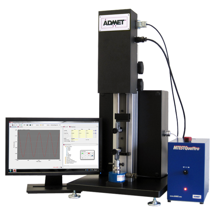
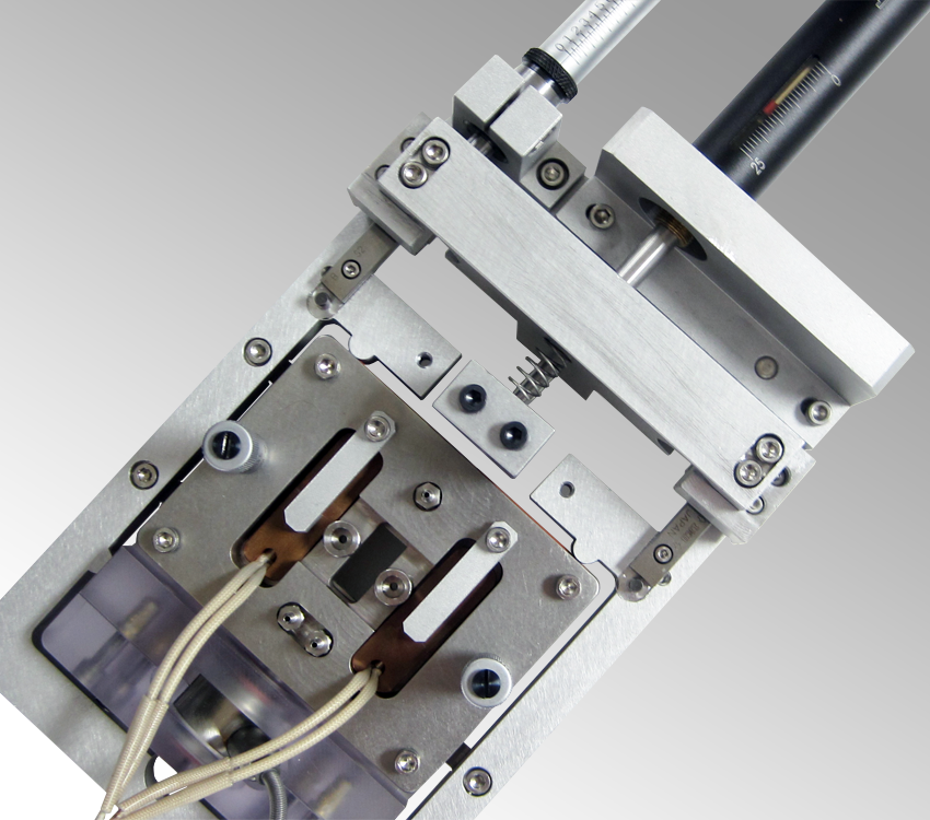
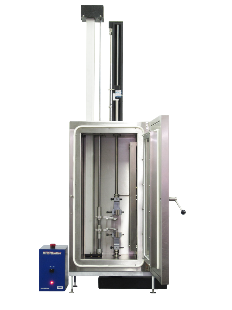
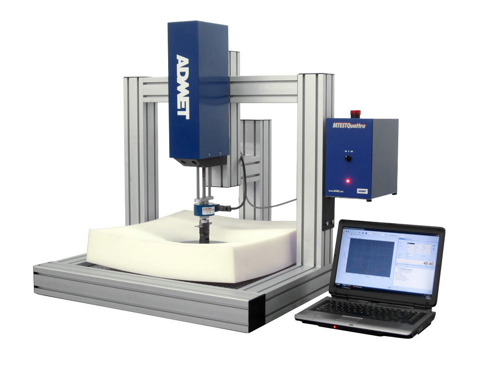
Orlando, FL- October 5, 2010 – ADMET, Inc., a provider of integrated materials testing systems, is showcasing their line of single, dual, and biaxial testing systems at the North American Spine Society’s 25th Annual Meeting. Booth #1891 The testing systems that will be featured are commonly used for testing biomedical materials and medical devices that require both static and dynamic testing profiles as well as uniaxial, biaxial, and long term fatigue.
ADMET testing systems are critical to ensuring the integrity of the mechanical parts of spinal implants, bone screws and plates, bone cement, and other fixation devices. ADMET’s MTESTQuattro software allows the user a flexible, easy to use interface, sophisticated analysis, and presentation quality reporting capability. ADMET testing systems comply with many ASTM specifications, including F1717, F1798, F2077, F2267, F543, F1541, F382, F384, F1264, and more.
See http://info.admet.com/specifications to see further description.
ADMET testing systems are utilized for tests that require both static and fatigue testing profiles. Common test types include compression, bend, shear, torsion, and biaxial. Users can easily set up testing profiles or utilize preset templates that have multiple segments, cyclic, ramp, sinusoid, or sawtooth waveforms. They can also adjust control gains and end point values on the fly or activate amplitude control to automatically adjust the end point values to ensure that desired targets are met. ADMET’s testing systems can be configured with numerous grips, fixtures, and other accessories including a T-slot table, fluid bath, heating and cooling chamber, fixtures for F1717, F2077, F543.

"ADMET’s systems are already being used in many research and production environments. We're finding that its cyclic testing capabilities are especially popular since it gives researchers an efficient way to certify their products to meet customer requirements and industry standards" said Richard Gedney, ADMET founder and president.
About ADMET
ADMET Inc., founded in 1989 and based in Norwood, Mass., combines high-quality products and services to deliver the most efficient and cost effective materials testing systems. Its products range from universal testing frames, to software and specialized control units, as well as grips and fixtures. Highly skilled engineers provide customers with personalized research and development services and support to make ADMET the most responsive materials testing equipment supplier.
ADMET's loyal customer base includes leading manufacturers, testing labs, researchers and universities in aerospace, automotive, biomedical, concrete, construction, metals, plastics, textiles and other industries. ADMET's products are widely distributed in North America, Central and South America, Europe, the Middle East and the Pacific Rim. ADMET can be reached at 781-769-0850 Ext. 21, sales@admet.com or by visiting http://www.admet.com.

Constitutive models are necessary to predict the mechanical behavior of biological tissues. However, biological materials present challenges in constitutive modeling due to their complex mechanical behavior. Their oriented fibrous structures often exhibit pronounced mechanical anisotropy. Due to anisotropy, stress strain data generated from uniaxial tests cannot be used to extrapolate to generalized three-dimensional constitutive equations. Since biological tissues are generally considered incompressible, planar biaxial testing allows for a two-dimensional stress-state that can be used to characterize their mechanical properties and validate the constitutive models.

Figure 1 - Diagram of a planar biaxial test setup.
Biaxial stress-strain measurements on soft biological tissues are generally difficult to perform. Some of the challanges include: small specimen sizes; gripping the specimens; differing gripping techniques producing inconsistent results; identifying material axes; large specimen-to-specimen variability; time-dependent changes due to biological degradation; and achieving homogeneity of deformation within the specimen.
Biaxial testing of biological tissues is performed using thin specimens, which are either a membrane in its native form or a thin section prepared from a thick tissue slab. The specimen is mounted to the biaxial device in trampoline-like fashion using thin threads (Figure 1), which allows the edges to expand freely in the lateral direction. Testing is generally performed with the specimen completely immersed in phosphate buffered normal saline (pH 7.4) at room or body (37◦C) temperature. The central target region must be sufficiently small and located away from the outer edges to avoid the tethering effects. Thus, in the central target region the stress and strain field is generally considered homogeneous.
Figure 2 - ADMET planar biaxial test system general arrangement.
ADMET's planar biaxial testing system is designed specifically for soft materials and biological tissues. The two orthogonal actuators can be programmed to move independently or in a coordinated motion under force or defromation control. The testing system includes suture racks for gripping the specimen in trampoline like fashion. The suture racks are pinned to the moving crossheads for easy installation and removal. Specimen baths and heating and cooling units for precise temperature control are also available. Various low force load cells and optical strain measurements provide accurate force-deformation data.
If you would like to ask an engineer a question or request more information regarding planar biaxial testing, please contact ADMET at 1-800-667-3220 or info@ADMET.com
More testing news
More testing specifications
ADMET was one of the sponsors of Plastics in Medical Devices held at UMASS Lowell Inn and Conference Center in Lowell, MA on Tuesday, April 20, 2010. The conference was co-organized by the SPE Medical Plastics Division, the ENE SPE Section and the UML Plastics Engineering Department.

The conference was focused on all aspects of Plastics and their use in the manufacture of medical devices. Attendees were engineers, scientists, and business professionals. 12 Guest Speakers presented information. Some of the speakers are listed below.
- Trends for Plastics in Medical Devices, Len Czuba, LC Enterprise Inc.
- High Performance Polymers for Medical Device Applications by Jeff Smith, Evonik LLC
- Hydrogel Catheter Design by Scott Epstein, Q Urological Corporation
- Plastics Technology for Minimally Invasive Medical Devices by Dan Lazas, PolyMedex Discovery Group.
- Application Testing for Medical Devices, Tao Xu, Exponent LLC
- What Healthcare Customers Really Want from Material Suppliers by Steve Schelgel, PolyOne.
- Copolyesters in Medical Devices by Scott Hanson, Eastman Chemical
The presentations covered a wide range of topics; science, manufacture and production, business, healthcare reform, and the issues facing plastics' companies in the medical devices industry.

Steve Tello From UMASS Lowell, M2D2- Massachusetts Medical Device Development Center, gave a presentation during lunch focusing on the business aspects of getting started in the medical device industry. According to a recent post, the M2D2 program in its first eighteen months of operation has helped 23 start-up companies and entrepreneurs bridge the gap between invention and production of new medical devices. We all enjoyed his presentation.

ADMET was a sponsor and exhibited their eXpert 7601, 1kN, single column testing system as well as running many testing videos showing various raw materials and finished devices being tested. Attendees loved the small footprint of the ADMET testing system and the flexible, MTESTQuattro, software interface used to control the testing frame. Many of the common plastic, rubber, and film ASTM standards, including ASTM D624, D1414, D412, F88, D882, Syringe test, and more.
The conference was well organized and everyone who attended was satisfied with the program. UMASS Lowell is planning more of this type of conference in the future. Stay tuned...
More testing news
Ask an Engineer about your application
Request more information from ADMET
All concrete testing laboratories produce essentially the same compressive strength test reports. So, how can a laboratory manager create a distinctive product while boosting profitability?
Speed Control
Concrete exhibits loading-rate sensitivity relative to compressive strength,1,2 so ASTM C39, "Standard Test Method for Compressive Strength of Cylindrical Concrete Specimens,"3 limits loading rate to 0.2 to 0.3MPa/sec (28 to 42 psi/sec). This helps ensure consistency within and among laboratories.
Almost 70% of the testing machines now in service are manually operated. The operator is therefore required to manually adjust a valve to achieve a loading rate within specification. Unfortunately, these adjustments can be inaccurate, particularly because only about half of the concrete testing machines now in service have any provision to indicate load rate. A fifth of testing machines now in service do have digital indicators that provide loading rates, but the attained rates aren't verifiable after the tests.
Figure 1 - ADMET MegaForce II Automatic Concrete Testing System.
A Step in the Right Direction
To address the shortcoming of nonverifiable loading rates, manually operated machines are now being offered that calculate and report the average loading rate according to ASTM C39 requirements and can generate load and stress versus time curves to verify that a test was performed according to specification. They also offer digital indicators that provide a live indication of loading rate. These systems don't, however, eliminate the possibility that an operator could perform tests at rates exceeding ASTM C39 limits.
More Control
There is clearly a need for an automatic concrete testing system that can control loading rate. Control systems used on conventional universal testing machines, however, aren't appropriate for concrete testing applications. Most concrete testing machines in operation are hydraulically actuated and operate at oil pressures as high as 68.9 MPa (10,000 psi). In contrast, conventional servo-hydraulic testing systems operate at maximum pressures of about 31 MPa (4500 psi). These systems therefore have large-and very expensive-actuators, and their high cost precludes them from widespread use in concrete testing.
Over the past six years, ADMET, Inc. has offered a low-cost, reliable, automatic concrete testing system that addresses these issues. As shown in Fig. 1, the MegaForce II automatic testing system works with compression machines that operate to 68.9 MPa (10,000 psi), prevents the operator from overriding the testing process, and provides verification of loading rates-all for 50 to 75% less cost than for a comparable servo-controlled testing machine. The automatic testing system can be installed on new machines or retrofitted to existing machines, generating further cost savings.
References
1. Carino, N.J.; Guthrie, W.F.; Lagergren, E.S.; and Mullings, G.M. "Effects of Testing Variables on the Strength of High-Strength (90 MPa) Concrete Cylinders," High-Performance Concrete: Proceedings, ACI International Conference, Singapore, 1994 (SP-149), V.M. Malhotra, ed., American Concrete Institute, Farmington Hills, MI, 1994, pp. 589-632.
2. Han, N., and Walraven, J.C., "Properties of High-Strength Concrete Subjected to Uniaxial Loading," High-Performance Concrete: Proceedings, ACI International Conference, Singapore, 1994 (SP-149), V.M. Malhotra, ed., American Concrete Institute, Farmington Hills, MI, 1994, pp. 269-288.
3. ASTM C39/C39M-05e1, "Standard Test Method for Compressive Strength of Cylindrical Concrete Specimens," ASTM International, West Conshohocken, PA, 2005, 7 pp.
Click here for more information on ADMET's concrete testing systems.
Fiber reinforced concrete (FRC) is finding increased use in construction. FRC offers several advantages over rebar or wire mesh reinforced concrete including increased crack resistance, ductility, energy absorption, impact resistance and residual strength. FRC can also significantly lower materials and labor costs compared to rebar or wire mesh reinforced concrete.
ASTM C1609, Standard Test Method for Flexural Performance of Fiber-Reinforced Concrete (Using Beam With Third-Point Loading), is one specification governing the testing of Fiber Reinforced Concrete Beams.
C1609 requires the use of a closed-loop, servo controlled compression testing machine. The test is run at specified net deflection rates as measured at the mid-span point of the beam.
The testing machine must be capable of controlling at very slow speeds. Electromechanical testing machines are best suited for this type of application.
Figure 1 shows a typical test setup to perform the C1609 test. It is a third-point loading fixture with two support points and two loading noses on the top of the beam. A rectangular jig surrounds the beam and is mounted on the beam's neutral axis directly over the supports. Two displacement transducers, one on each side of the beam, are mounted mid-span to measure beam deflection. The output of each transducer is averaged together to provide the net deflection measurement. This configuration ensures accurate measurement of mid-span deflection and minimizes errors due to concrete specimen twisting or seating in the supports.
Figure 1. Typical ASTM C1609 Test Fixture.
The test is run at a specified net deflection rate to a net deflection of L/600 (where L is the support span distance). After which it can be run at a higher specified net deflection rate until the specified endpoint.
Table 1. ASTM C1609 Net Deflection Testing Rates.
ASTM C1609 data analyses include 1st Peak Strength, Ultimate Strength, Residual Strength at L/600, Residual Strength at L/150 and Toughness, which is the area under load versus net deflection curve from 0 to L/150.
Figure 2 - Stress versus net deflection curve with ASTM C1609 analysis results.
Click here for more information on ADMET's concrete testing systems.
Torque, also called moment or moment of force, is the tendency of a force to rotate an object about an axis or pivot. Torque is rotational force. Twisting the female to male fitting, to remove or replace the connection, is an example of applying torque. The amount of torque developed is proportional to the force applied and to how far from the center of the rotation the force is applied.
When making manufacturing decisions for medical device applications and other material testing applications it is important to know the product's torque and angle capacity. How easy or difficult it is to twist a cover, connector, or switch is important to the practitioner using the product. Biopsy needles are inserted and then twisted to remove a sample. If the value of force needed to insert the needle was not calculated precisely, it could effect the practitioner's ablity to retrieve a proper sample. If a conical fitting was not tightened to it's full torque capacity, there may be liquid leakage, air leakage, stress cracking, and/or separation.
ADMET suggests the following systems to perform a range of static and fatigue torsion tests.

Vertical eXpert 81T 20 Nm Torsion Tester
Horizontal eXpert 81T 2Nm Torsion Tester
eXpert 81T Torsion Testing Systems
- Vertical or Horizontal orientation
- Tabletop Torsion Testers// 0.1Nm to 500Nm(4,500 in-lb)
- Floor standing Torsion Testers //to 11,000 Nm (100,000 in-lb)
- Employ a linear slide design to allow:
- maximum torsional stiffness
- minimal axial friction
- A reaction torque transducer is attached to a movable tail stock mounted on a linear slide
- Interchangeable torque transducers available
- Linear slide dimensions sized to accommodate specimen lengths
- The tail stock can be left free floating or clamped during testing
- Most systems have unlimited rotation in the clockwise and counter clockwise directions
- Ability to apply axial forces through a dead weight pulley system or optional linear actuator
- Optional linear displacement transducer to measure tailstock movement
- Speed range - determined by customer input. Torsion fatigue testing systems are capable of performing sine, square or sawtooth waveform amplitude control to 20 Hz
- Data export capability - .csv, ascii delimited, .jpg, bitmap image
- FULLY Customizable-The length of the test bed, servo motor, and gearing is modified to accommodate varying specimen lengths, capacities and test speeds.
Biaxial Tension/Compression/Torsion systems are available.
Grips and Fixtures
eXpert 81T Torsion Testers can be equipped with collets, chucks and drive sockets to hold and twist your specimens.
- ADMET will also machine custom adapters to accommodate unusual shapes and sizes
- Environmental baths with heating and cooling systems meet aerospace and medical device test requirements.

ASTM and ISO Torsion Test Standards
ISO 594/1-1986 describes the dimensions, testing profile, and parameters for testing conical fittings with a 6% (luer) taper for hypodermic syringes, needles, and certain other medical equipment, such as transfusion and infusion sets. This standard covers rigid and semi-rigid materials for guaging and performance.
- Several of the mechanical tests in section 5, figures 4+5, require torque testing. In ISO 594-1, an axial force of 27.5N(5lbs) is applied for 5 seconds while applying 0.1Nm torque load to an angle of 90 degrees.
Recommended system for sections 5.2.1, 5.3.1.1, 5.5.1 is an ADMET eXpert 81T Torsion Tester with MTESTQuattro Torsion PC Based controller or with an eP Torque digital controller, dead weight pulley, and grips. Request a quote
ASTM F1541- External Skeletal Fixation Devices This test method has many different annexes for testing Fixator connectors, joints, rings, pins, sub-assemblies and constructs.
Recommended systems-
- 81T Torsion Tester or
- eXpert 7600 single column testing frame or
- eXpert 2600 Biaxial or Triaxial Tester.
- MTESTQuattro Torsion, MTESTQuattro, or MTESTQuattro Integrated. Depending on which annexes you would like to perform.
- Request a quote or Ask an Engineer a Question
ASTM A938-07 - the torsional strength of wire.
Recommended system 81T Torsion Tester, 12Nm, MTESTQuattro Torsion, Collet Chuck, 5c Collet, Dead Weight Pulley System Request a Quote
Request Torsion Testing Specifics...
More ADMET Videos...
More ADMET Specifications...
Ask an engineer a question
Contact ADMET at 1-800-667-3220 or sales@ADMET.com for more information on all of our Testing Systems.
For 20 years ADMET's focus has been on producing leading edge mechanical testing systems that are reliable, exceed ASTM/ISO accuracy requirements, and are easy to learn and use. During this time we have remained steadfast to two founding principles; a willingness to tailor our systems to meet your needs; and to provide efficient and responsive customer service; thus giving you the confidence to test with certainty.
ADMET trainer conducting an MTESTQuattro(R) Materials Testing System on-line training session.
Consistent with our founding principles, ADMET is now offering on-line training for all products, controllers and software. Using GOTO Meeting, ADMET will provide 1 to 2 training sessions at up to 1 hour each. At a minimum, each session will cover:
- How to setup and run a test
- How to view results and generate reports
- How to save and recall test methods
Afterward, the ADMET trainer will open the session up for questions. Participants will then be able to ask questions about the operation of ADMET systems or about testing in general.
On-site training is also available. However, most users do not require it, especially after completing an on-line training session. To schedule your on-line training session, call 800-667-3220 or click here and submit the form.
Metallic Bone Plates need to undergo several tests before gaining approval as internal fixation devices of the skeletal system. One standard, ASTM F382-99, defines the test methods for single cycle bend testing (annex A1) and for determining the bending fatigue properties (annex A2) of metallic bone plates. A summary of the test methods for annex A1 and A2 follows. For a complete description of ASTM F382-99, refer to the specification from the ASTM International organization.
Annex A1- ASTM F382-A1 measures the bending stiffness, bending structural stiffness, and bending strength from a single cycle bend test on a metallic bone plate.
Annex A1 is used to determine values for the mechanical response of bone plates to specific bending loads and provides some insight into the mechanical response of the subject bone plate. The bone plate is positioned on a 4 point bend fixture (shown below) installed in an Universal Testing Machine (UTM). The bend fixture should use cylindrical rollers with diameters between 6-12 mm. The recommended test configuration locates the loading rollers at one third points. The spacing of the rollers, however, is dependent on the location of the screw holes in the bone plate. Apply bending moments of increasing magnitude via crosshead position rate control. Generate a load versus load point displacement graph. Determine the bending stiffness, bending structural stiffness and bending strength.


To perform Annex 1, the 4 point bend fixture above can be used on an ADMET eXpert Single or Dual Column Universal Testing Machine Frame. ADMET has 2 types of controllers to set the speed, load, and position limits of the test. (MTESTQuattro and eP digital push button)
Annex A2 - Test Method for determining the bending fatigue properties of metallic bone plates.
This test method is used to determine the fatigue life at a specific or over a range of bending moment levels. It may also be used to estimate the fatigue strength for a specific number of cycles. The bone plate is positioned in a 4 point bend fixture so that a bone plate's section that would normally bridge the fracture site is subjected to a uniform bending moment. The bone plate is subjected to a constant amplitude constant frequency sinusoidal bending moment which is continued until the specimen fails or the runout cycle count is reached. The data generated from each plate test is used to create a M-N diagram (Bending Moment vs Number of Cycles). Typical cyclic frequencies and runout counts are 5 Hz and 1 million cycles, respectively.
Another Intermedullary Fixation Device standards, ASTM F1264, requires a static and fatigue 4 point bend test, as well as a static torsion test. Also, bone screws are subject to standard torsion testing. (ASTM F543 and ASTM F115)
1-800-667-3220 ADMET, Inc. call or email sales@ADMET.com any questions.
Spinal Implants are tested according to several ASTM standards. ASTM F1717 is intended to provide a basis for the mechanical comparison among past, present and future spinal implant assemblies. Three static and one fatigue mechanical test of a spinal construct are governed by ASTM F1717. The three static tests are compression bending, tension bending and torsion. The fatigue test is a compression bending test. The mechanical tests are conducted using simplified loading schemes and do not attempt to mimic the complex loads of the spine. An outline of the four test procedures is as follows:
Static Compression Bend Test - Load at a crosshead displacement rate not to exceed 25 mm/min and record the load vs displacement curve. Calculate displacement at 2% offset yield, elastic displacement, compressive bending yield load, compressive bending stiffness, compressive bending ultimate displacement and ultimate load.
Static Tension Bend Test - Load at a crosshead displacement rate not to exceed 25 mm/min. and record the load vs displacement curve. Calculate displacement at 2% offset yield, elastic displacement, tensile bending yield load, tensile bending stiffness, tensile bending ultimate displacement and ultimate load.
Static Torsion Test - Load at a rate not to exceed 60 deg/min and record the torque vs angle curve. Calculate angle at 2% offset yield, elastic angle, yield torque and torsional stiffness.
Compressive Bending Fatigue Test - Apply a constant load amplitude sinusoidal control profile at no faster than 5Hz. A constant load ratio, R, for all tests should be established and should be greater than or equal to 10. Evaluate two specimens at the initial fatigue loads. Determine the maximum run out load based on no samples failing prior to 5 million cycles. Continue fatigue testing pairs of specimens until the difference between the load at which a specimen fails and the run out load is no greater than 10% of the compression bending ultimate load.
ADMET biaxial universal testing systems are available for static only or for both the static and fatigue tests outlined above. These tests require specific fixturing described in the F1717 specification and can be provide by ADMET.

ADMET eXpert 2610 5kN - 10Nm Biaxial Tension, Compression, and Torsion Testing System equipped with the MTESTQuattro controller for static tests. System is shown with a multi axis load cell capable of measuring Fx, Fy, Fz and Mz.
The Orthopedic Tissue Engineering and Materials Lab at the University of North Carolina Charlotte (UNCC) was the winner of ADMET, Inc's 20 year anniversary celebration biomedical testing system giveaway. Drs. Ahmed El-Ghannam and Nigel Zheng at UNCC head a research team involved with the use of bioactive ceramic and bioactive ceramic-polymer composites as orthopedic fixation devices. To fulfill their testing needs, ADMET has awarded the team an eXpert 81T 20 Nm (177 in-lb) Vertical Torsion Testing System equipped with the PC based MTESTQuattro® Materials Testing System and an immersion bath.

ADMET eXpert 81T Vertical Torsion Testing System for testing bioabsorbable bone screws according to ASTM F2502.
Drs. El-Ghannam and Zheng will use the torsion machine for testing bioactive ceramic-polymer composite orthopedic fixation devices according to ASTM F2502 Annex A1 & A2. Test method F2502-A1is used to measure torsional yield strength, maximum torque and breaking angle; while F2502-A2 is used to measure insertion torque for the bioactive screws.
Example torque vs. angle plot of a screw twisted to failure. Included on the plot is the 2 deg offset yield line.
You can find more information on bone screw torque testing at ADMET's Biomedical webpage.
More testing news...
More testing videos...
Ask an engineer a question- click here